Contents
This deck, handrail and steps project required a building permit. This tutorial covers aspects of the project’s construction, along with some of the plans that were submitted to the authority when applying for building permission.
Prelude to the construction
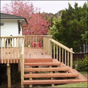
The owners wanted a hardwood deck coming out from their back door with spreading steps down to the yard.
The Plans
These are some of the plans that were drawn up to obtain a building permit for a deck.
The Site Plan
The site plan shows the placement of the proposed new deck in relation to the existing house along with the site boundaries, location of services (storm water, sewer etc.) The site plan also shows the road frontage with road name and an indication of North.
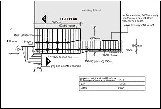
The Flat Plan
The flat plan or footprint plan is an arial (looking down) view of the proposed deck. It shows the overall dimensions of the project and other information such as footing placements, bearer and joist placement, and spacings between joists.
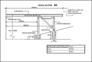
The Cross-Section Plan
The cross section plan is a plan taken from a cross section of the flat plan. The cross section shows construction, lumber sizes and footing size. A detail plan is sometimes accompanied to give clearer detail. A detail plan is a blow up (magnified) part of the plan.
Specifications are sometimes drawn on this page (material types, sizes etc).
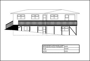
The Elevation Plan
The elevation plan is more like a drawing of the outside of the addition rather than a plan, although is still drawn to scale. The elevation plan gives a good perspective of the addition to the untrained eye.
Constructing the deck
The deck construction. Click on any red text for an explanation.
- The deck was built to the dimensions and specifications of the plans. The deck was profiled out and the holes were marked, dug, and then inspected by the building inspector.
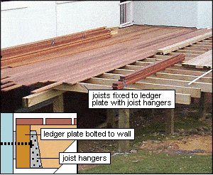
The treated posts, 125×125 (5×5) and slightly over height, were concreted in place with 100mm (4″) of concrete beneath each post. The concrete was left to cure. - The heights of the ledger plate and posts were determined by using a water level. The 150×50 (2×6) ledger plate was bolted to the house using 12mm (1/2″) galvanized coach screws every 1200mm (48″). The posts were trimmed off at the appropriate height. The treated bearers 150×100 (4×6) were fixed on top of the posts.
Next
- The joists were fixed in place, square off the building and spaced at 450crs (18″ O.C.). The joists were fixed to the ledger plate with joist hangers and fixed on the bearers with galvanized nails and Z nails.
- The joists were over length, so they could be trimmed off later.
- The hardwood decking was fixed in place.
For instructions on how to lay decking straight, click here.
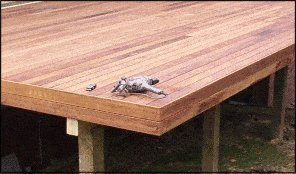
- Once the decking boards were fixed in place, the ends were trimmed and two hardwood decking boards were fixed around the perimeter for a decorative (rather than structural) finish. (see below)
Constructing the handrall
- Handrails on decks are governed by certain criteria.
- Enquire at your local building department to see what criteria is required.
Other notes
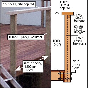
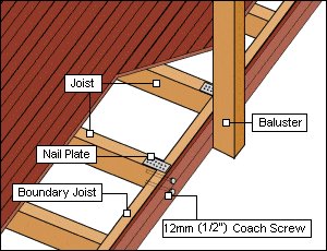
- The 100×75 (3×4) Balusters were spaced not more than 1800mm (72″) and bolted to the boundary joist with 2 galvanized 12mm (1/2″) bolts.
- The joists each side of the balusters were fixed to the boundary joist with nail plates top and bottom, and also with two 12mm (1/2″) coach screws per joist.
- The 50×50 (2×2) treated uprights were fixed in place, nailed to the boundary joist at the bottom, and nailed to the batten and top rail, at the top.
- The uprights were spaced so no gaps were wider than 100mm (4″).
Constructing the steps
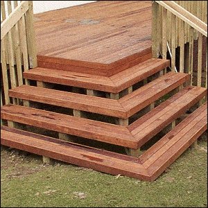
- The steps on this deck are not standard steps, but more a feature. Steps are also governed by a certain criteria, such as treads must be a minimum of 280mm (11 1/2″), rises must be a maximum of 185mm (7 3/8″) high and toe recess should be between 15mm (5/8″) and 25mm (1″).
- For construction details on making standard exterior steps click here
- Enquire at your local authority to see what criteria is required.
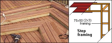
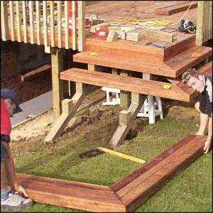
- The steps were made up separately on an even surface (the deck). Step frames were constructed from 75×50 (2×3) treated lumber. The frame width was to accommodate three hardwood decking boards with a 5mm (3/16″) gap between them. The length of the first step frame was 1200mm (48″) along both runs, and every other step frame was progressively 300mm (12″) longer along each run.
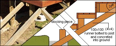
- Four 100×100 (4×4) runners were put in place to bear the steps.
- The top of the runners were bolted to the joists on one side of the deck, and solid nogs/blocks on the other. After ensuring the runners were the desired pitch (in this case 31 degrees), concrete was placed around the bottom.
- 100×100 (4×4) treated blocking pieces were fixed on the runners to take the front edge of the step frames (see above illustration).
- The pre-made steps were then lifted and fixed in place on the runners and blocking pieces. An additional runner with blocking pieces was then placed under the center join of the steps.
- The handrail was fixed to the side of the steps, a bit of a clean up, and all finished.

